MCS-170 Project 6: CPU DataPath - Part I

Project Task

In class, we have begun a discussion of how the Central Processing Unit (CPU) of a computer functions. The CPU is one of the three main components of the Von Neumann architecture of a computer -- the other two components being the memory and the input/output system. 

In this lab, you will use a CPU simulator to investigate the basic path that data and instructions take as they move among the subunits of a CPU.  During the lab you will be asked a series of questions. Record your answers and turn them in to the instructor at the end of the lab period.


In Lab

The CPU is the brains of a computer.  The CPU grabs data and instructions from memory, executes the instructions using the data, and stores results back to memory.  The instructions that a CPU can carry out are known as the computer's machine language.  In part II of this lab we will investigate machine language instructions in detail.

The CPU carries out its duties by dividing up its work into a set of subunits.  These are:
data path
 
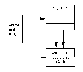
CPU Subunits - Note the two buses connecting the registers to the ALU.
This is due to the fact that ALU operations like addition operate on two data values,
whereas the result is a single value (the bus from the ALU back to the registers)

The CPU DataPath: The path that data follows within the CPU, along buses from registers to ALU and back is called the CPU Datapath.  Everything a computer does, whether playing an MPEG file, or a video game, is, in the end, essentially a sequence of very primitive operations whereby data is moved from registers to the ALU, operations are performed on that data, and then the result is returned to the registers. A single round of  Registers -> ALU -> Registers is called a CPU Datapath Cycle.

In order to better understand this cycle, we will investigate a very simple simulation of a CPU datapath.  The simulator has 4 registers and an ALU (with operations for addition, subtraction, bitwise-AND, and bitwise-OR). This simplified CPU does not have a Control Unit. Instead, we will act as the control unit, selecting the input registers, the ALU function, and the output register for the result, by clicking on the appropriate knobs in the simulator.

To start, open a second browser window and in this window go to the simulator at this site -- http://www.prenhall.com/reed/Chapter14/datapath.html
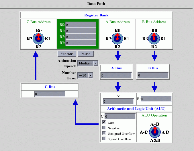
You will see a page with the simulator as shown.
datasim1

The simulator uses text boxes for registers (the boxes labeled R0, R1, R2, and R3).  There are two buses from the registers to the ALU, these are labeled A and B.  We select which register will be accessed for data on the buses by setting the knobs labeled "A Bus Address" and "B Bus Address." Also, there is a bus ("C") from the ALU back to the registers. We control which register the data travels through along the C bus by another knob.

The ALU will do four basic operation as described above. We select which operation it will do by the use of the knob labeled "ALU Operation."

Control through this datapath is started by clicking the "Execute" button. 

As an example, set registers 0 and 1 to be 43 and -296, respectively. (We are following the example on page 253 of the text.) Then, set the A bus knob to point to R0, and the B bus knob to R1. Set the C bus knob to R2.  Leave the ALU knob in its default position, i.e. at the "A+B" position.  Then, click the "Execute" button. The simulator will slowly show how data travels from the registers along the buses to the ALU and then how the result travels along bus C back to the registers.  Closely watch how this datapath is executed before moving on, so that you understand what the simulator is showing.

EXERCISE 1: How must the knobs in the Computer Datapath Simulator be set in order to subtract the contents of register R1 from register R3, and store the result in R2?  Set the registers and knobs to carry out this example, with register 1 set to 38 and register 3 set to 128. Check that the datapath works correctly.

EXERCISE 2:
  How must the knobs in the Computer Datapath Simulator be set so that the value initially in R2 is doubled and the result stored in R1? 

EXERCISE 3:  How many CPU cycles would be required in order to add the contents of registers R0, R1, and R2 and store the result in R3? Describe the settings for each of the cycles.

The simulator allows one to enter numbers in either binary form or decimal form.  Note on the simulator the area labeled "Number Base."  Type the number 64 into R0 and then choose "2" from the set of choices that will pop up when you click on the box to the right of the label "Number Base." The number in R0 is now displayed in binary format. Note that the binary form of 64 shown in R0 is 0000000001000000 and not  10000000 as one would expect. There is a good reason for this. Remember that numbers stored in a computer are stored with a fixed set of binary digits, or bits. The fixed length for a number in our simulator is 16 bits. Thus, to define a number, we must specify all 16 bits of that number.

EXERCISE 4:  Use the Computer Datapath Simulator to determine what decimal values are represented by the following binary numbers. (Remember to fill out all 16 bits when you type the number into one of the registers)       101       100001       1000111
The ALU can do four basic operations -- addition, subtraction, bitwise-AND, and bitwise-OR. The bitwise AND of two binary numbers is represented by the knob position "A&B" in the simulator.  In a bitwise logical AND operation, each bit of a number is treated as a True or False value, with 1 being true and 0 being false. Thus the bitwise AND of 10 and 01 is 00, as the AND of the right-most bits is the AND of 0 and 1, which is 0, as is the AND of the first bits (1 and 0).
EXERCISE 5:  What should the bitwise logical AND of the numbers 101101 and 11 be? Use the Computer Datapath Simulator to determine the bitwise logical AND of the binary numbers 101101 and 11. (Again, remember to fill out all 16 bits when you type in a number)
EXERCISE 6:  What did you find most confusing in working with the Computer Datapath Simulator?

Project Report:

Hand in your answers to the exercises above.


Back to MCS 170 home page